

Assembly Guide
The unit is pre-assembled through Step [02] upon shipped. Please unscrew the M3 screws to separate the top and bottom cases, then begin from Step [03]
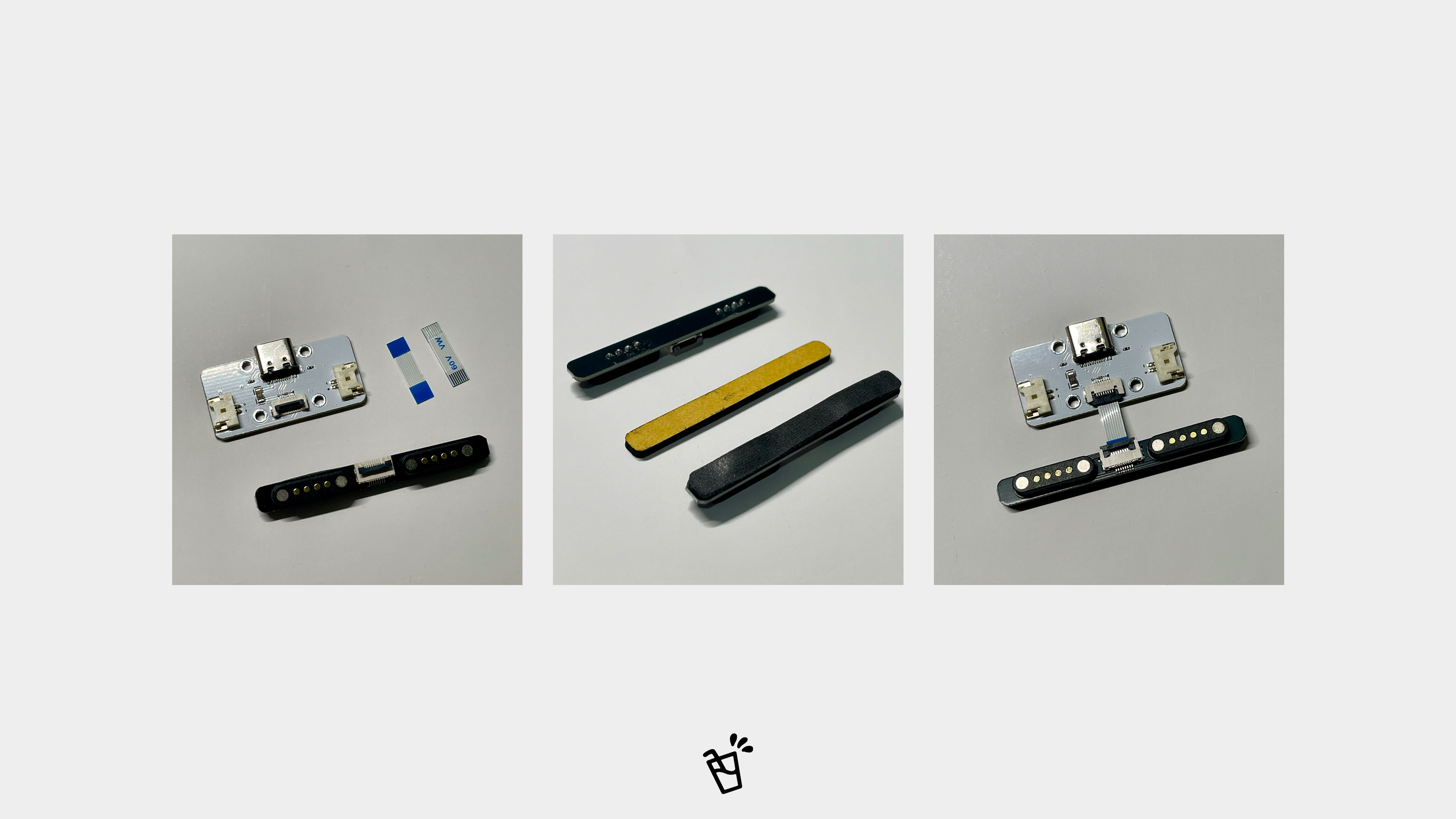
01 - Daughterboard Installation
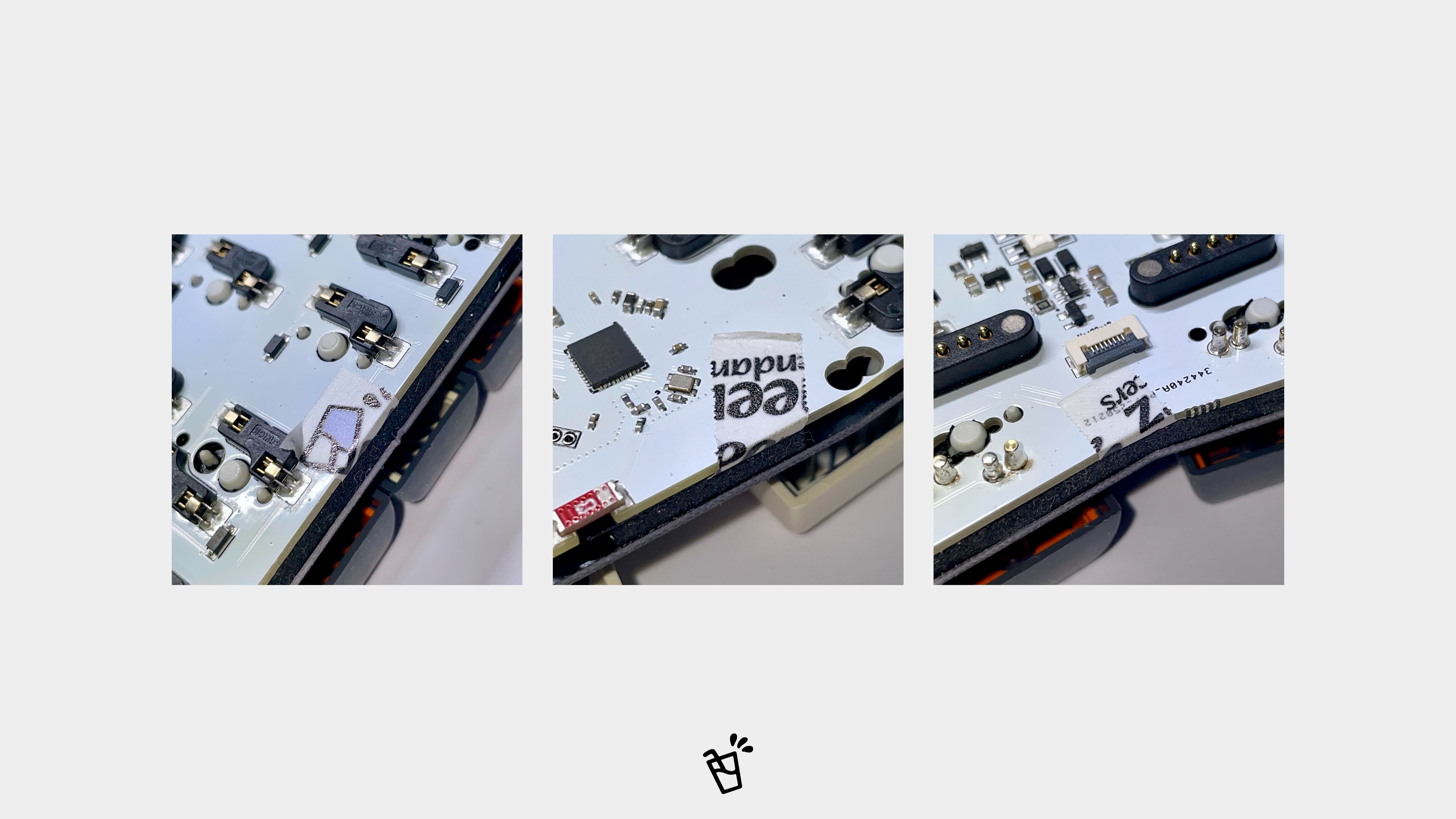
Apply the insulating foam to the back of the magnetic daughterboard.
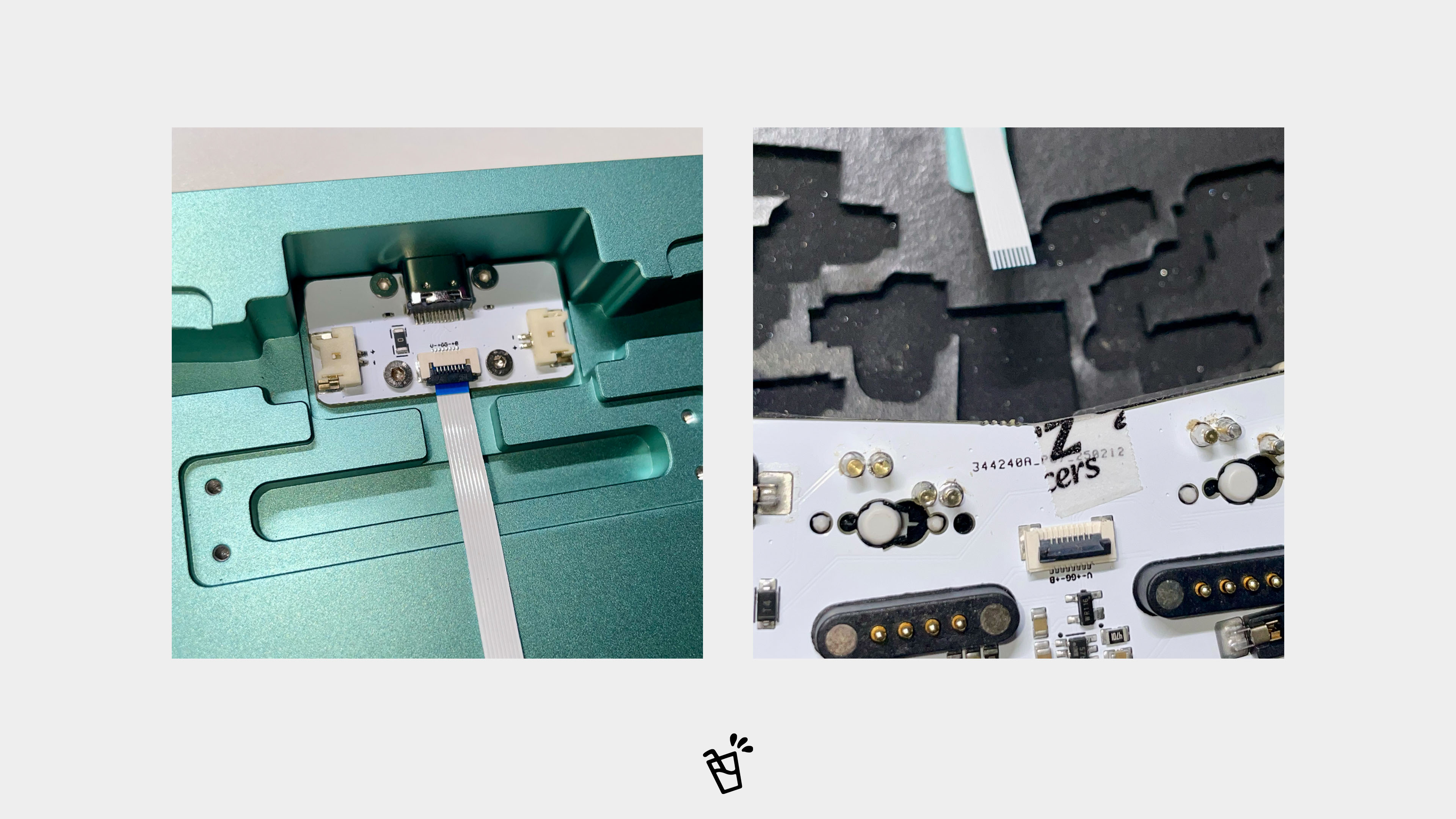
Connect the USB-C daughterboard to the magnetic daughterboard using a short, same-way FFC.
To connect, flip up the connector latch, insert the FFC, then press the latch down to lock it. The stiffeners on each end may differ slightly in length, but the cable itself is non-directional. Simply ensure that both blue stiffeners face upward during insertion.
Note: You must use the and insert it firmly.
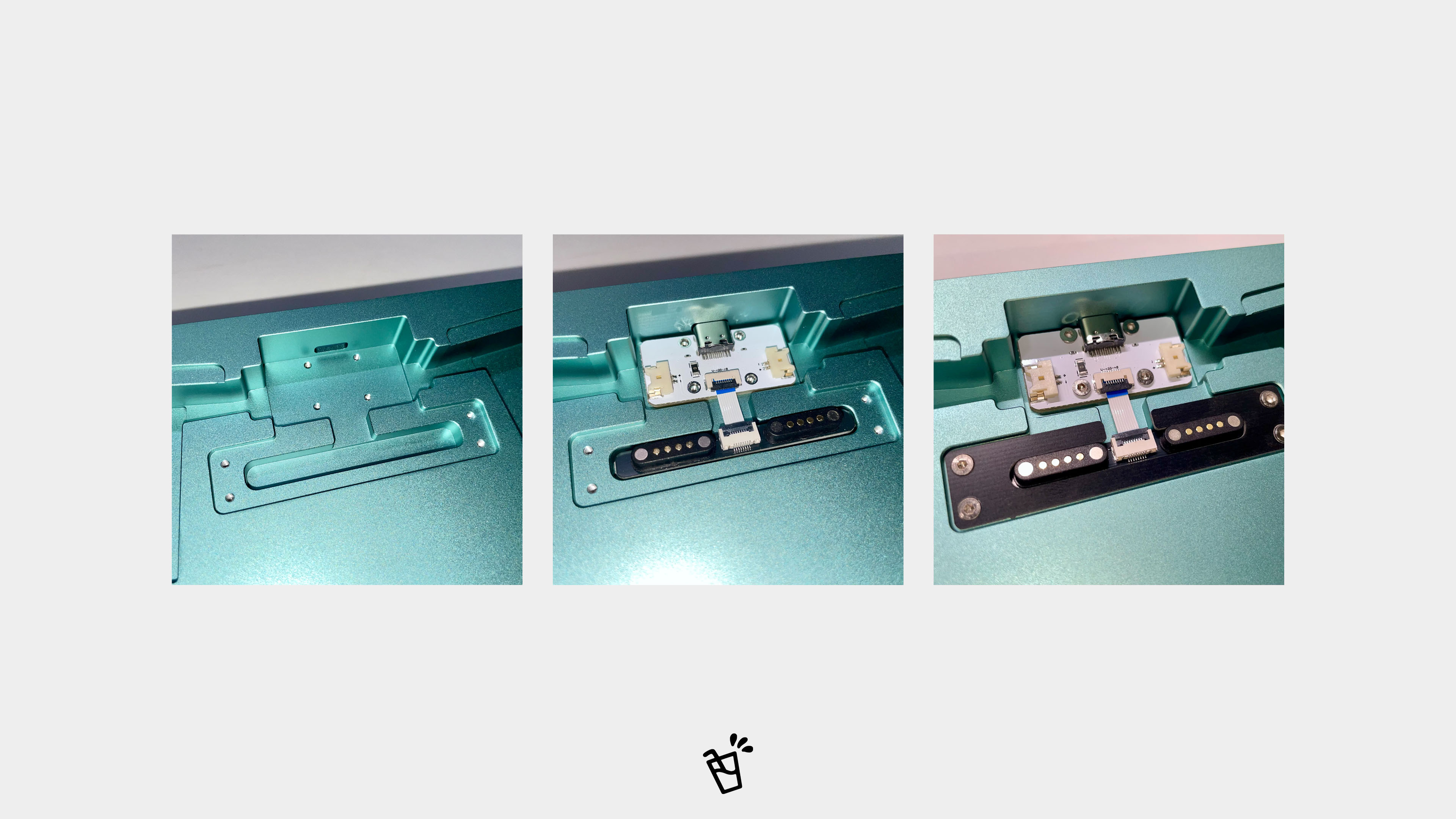
- Position the connected daughterboards into the bottom case and secure the USB-C daughterboard with M2 screws.
- Insert the magnetic daughterboard into its slot. Place the magnetic daughterboard retainer cover over it, ensuring the notch on the cover faces upward (toward the USB-C daughterboard) and matches the shape on the bottom case. Secure the cover with M2 screws.
Note: Ensure the countersunk side (the bevelled side) of the screw holes faces upward.
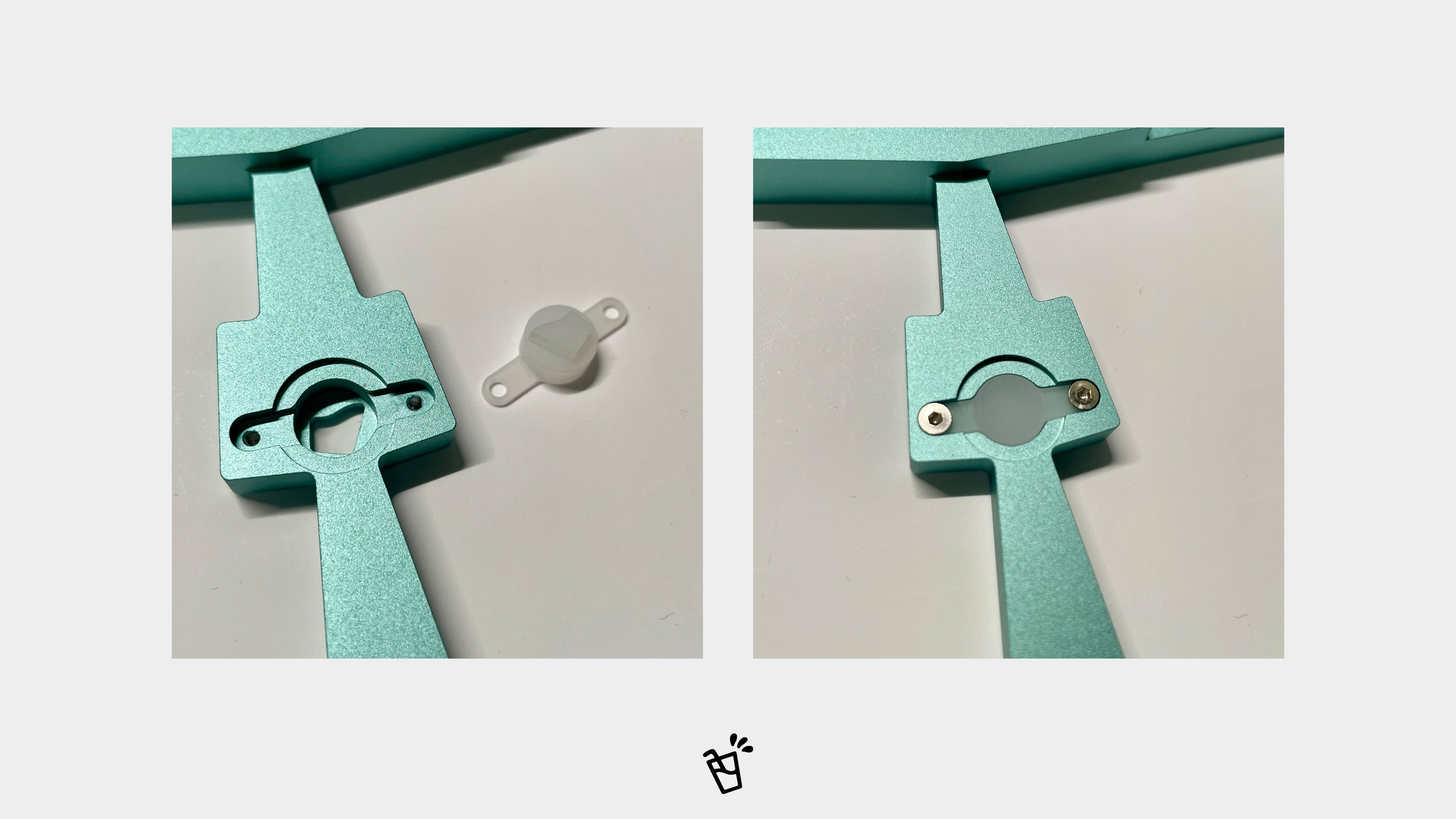
02 - Light Diffuser Installation
- Take the top case. Align the light diffuser with the central hole and secure it with two M2 screws.
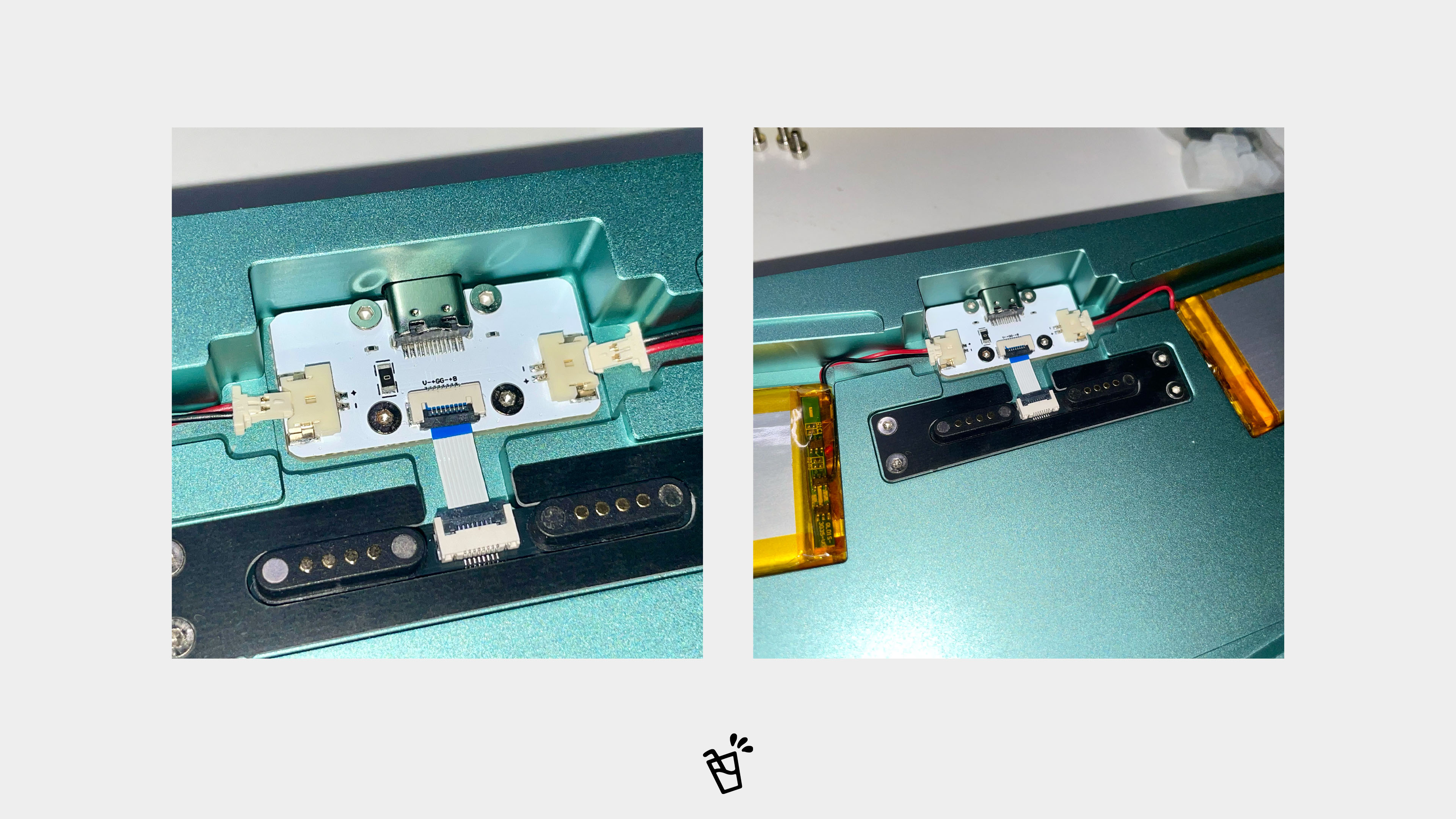
03 - Battery Installation
Connect each battery to its respective connector on the USB-C daughterboard, observing correct polarity as indicated on the board. Then place the batteries into the left and right battery compartments.
Battery installation is optional. Without batteries, the keyboard operates in wired mode only. Please note that key configurations may need to be saved manually. Refer to the Key Configuration Guide for details.
04 - Core Assembly
- First, assemble the core module externally. When positioning the IXPE Switch foam, use the included washi tape to temporarily secure it to the PCB. Use the included PCB Socket Reference Card to confirm the switch direction for each key position.
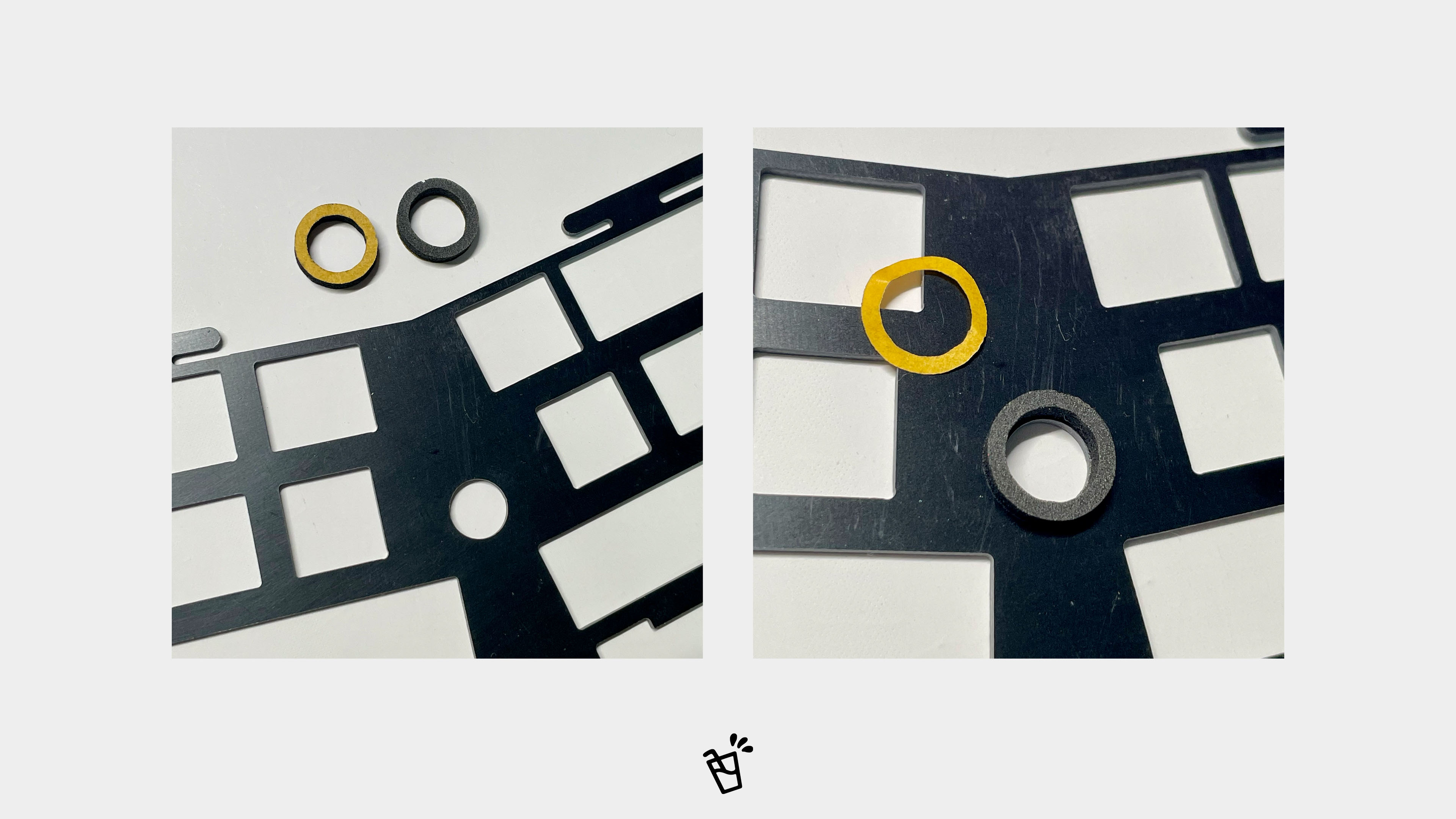
Attach the light-blocking foam ring to the central hole of the plate. Use tweezers for alignment to ensure the foam completely covers the hole.
Note: If the light-blocking foam ring is not installed, there will be slight light leakage.
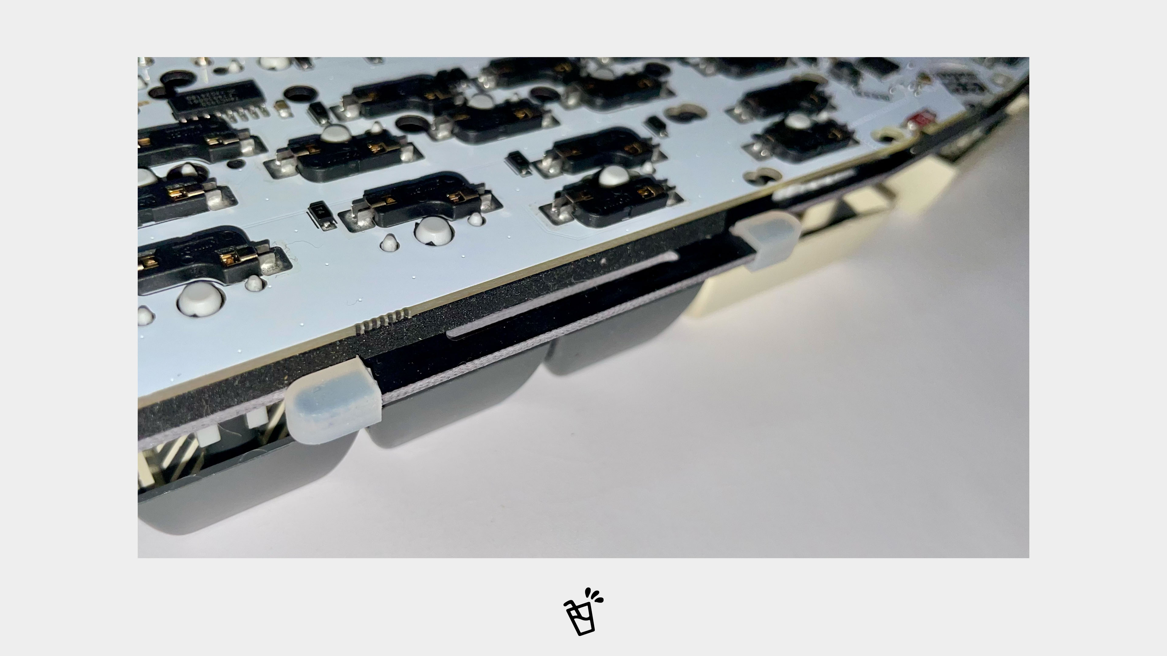
- Install the silicone gaskets onto the plate (8 in total). You can install the keycaps following this step.
05 - Final Assembly
Align the core assembly with the bottom case; the magnetic connectors will engage automatically. Ensure each silicone gasket fits completely into its slots in the bottom case.
You can first tilt the core assembly to engage the gasket slots on one side (e.g., the side closer to you) before seating it fully.
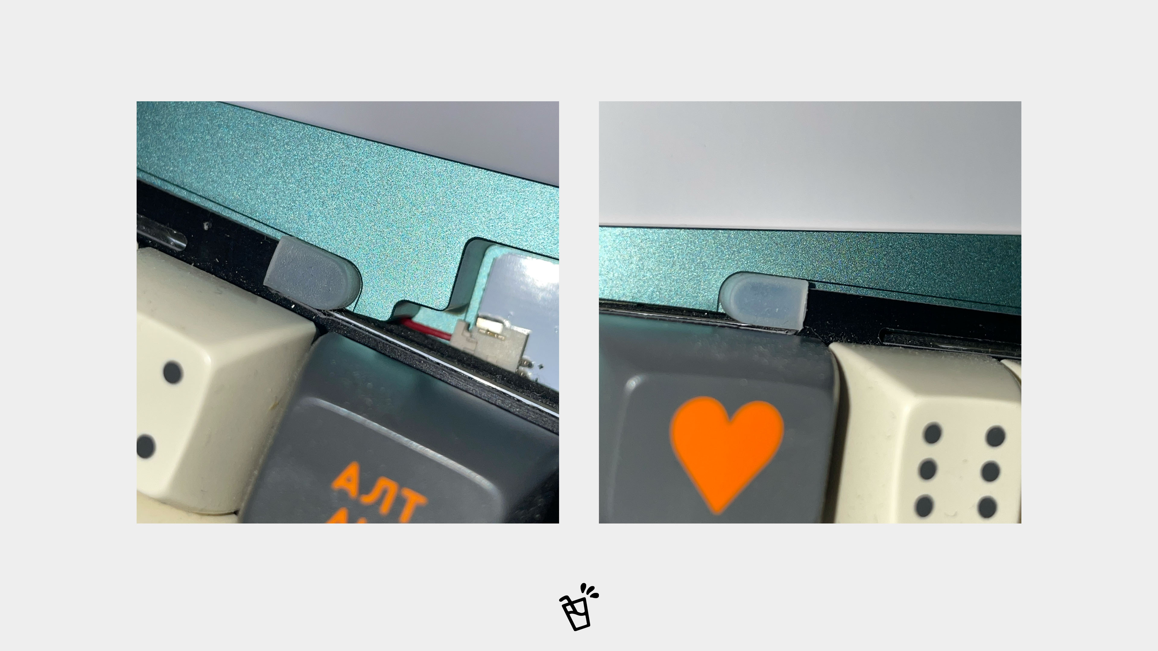
- Close the top case and secure the top and bottom cases with M3 screws. If you feel significant resistance when closing the case, one or more silicone gaskets may not be fully seated.
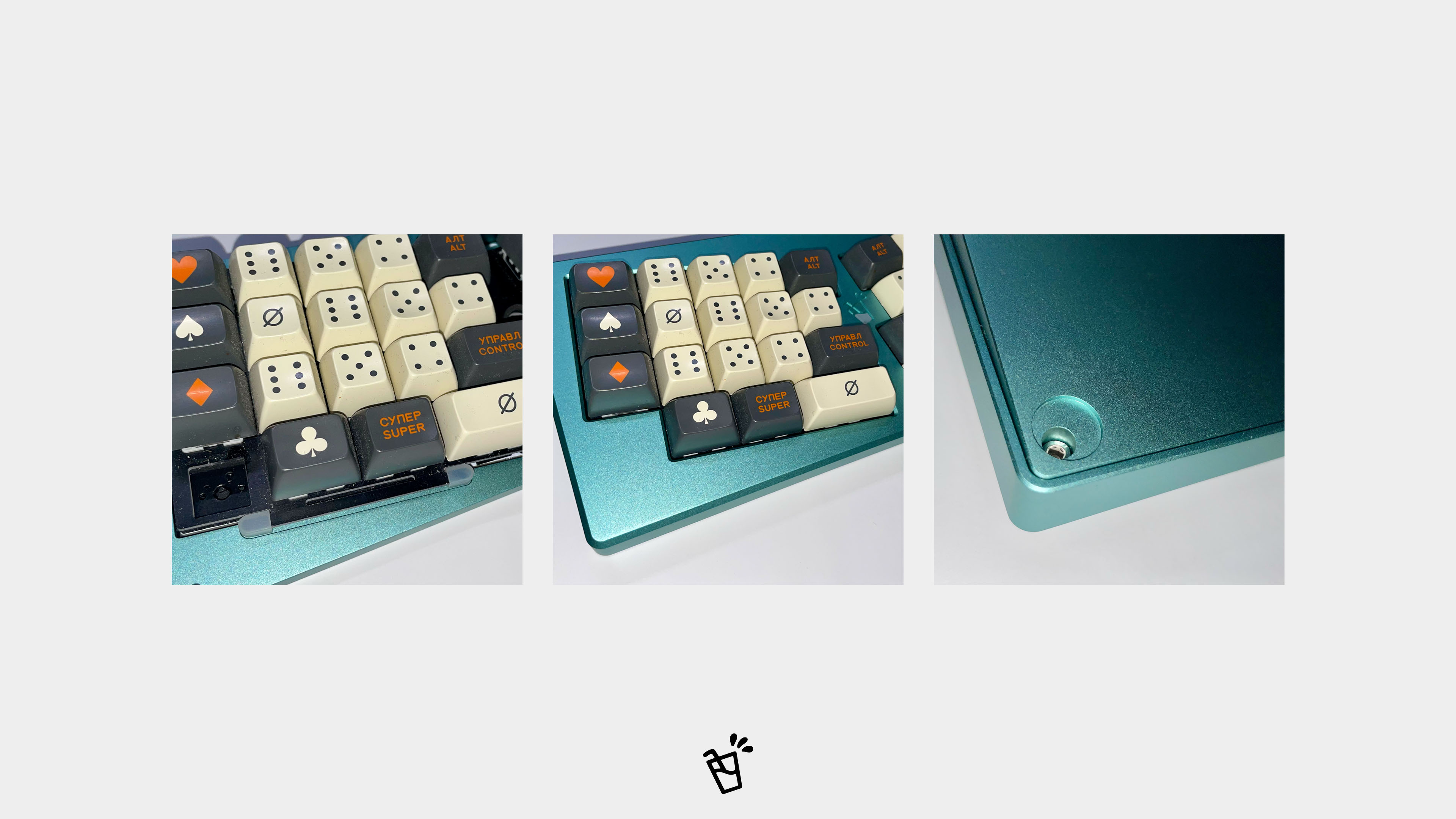
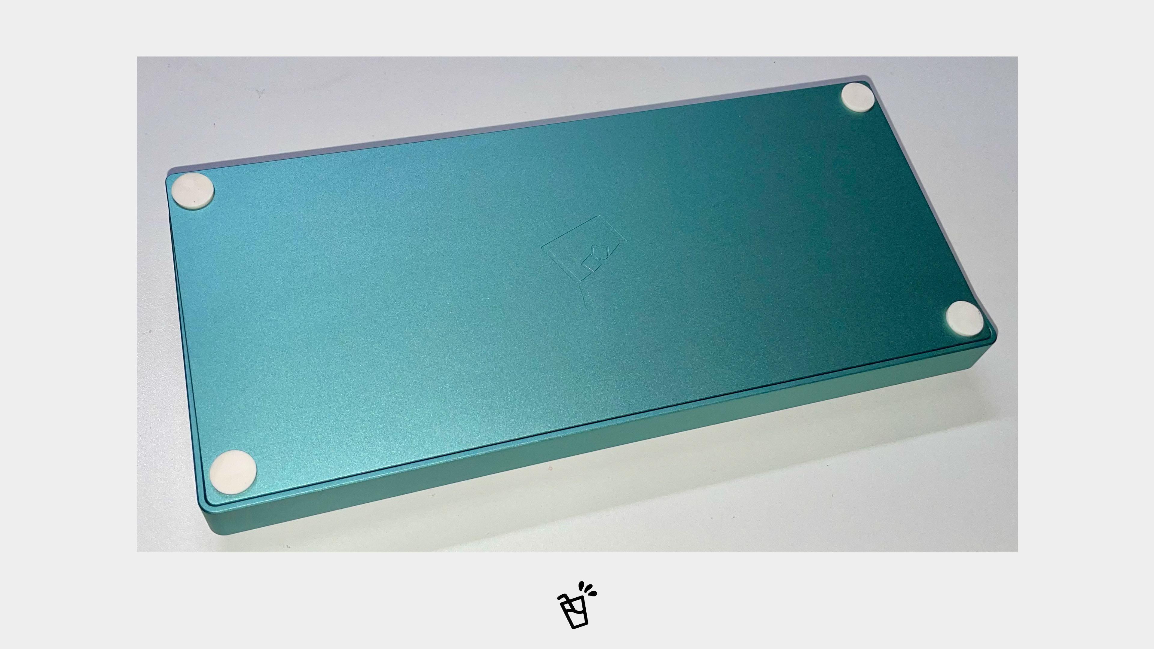
- Apply the foot pads over the screw holes. The included pads are 12mm in diameter and 2mm thick. You may purchase and install replacements in other specifications as desired.
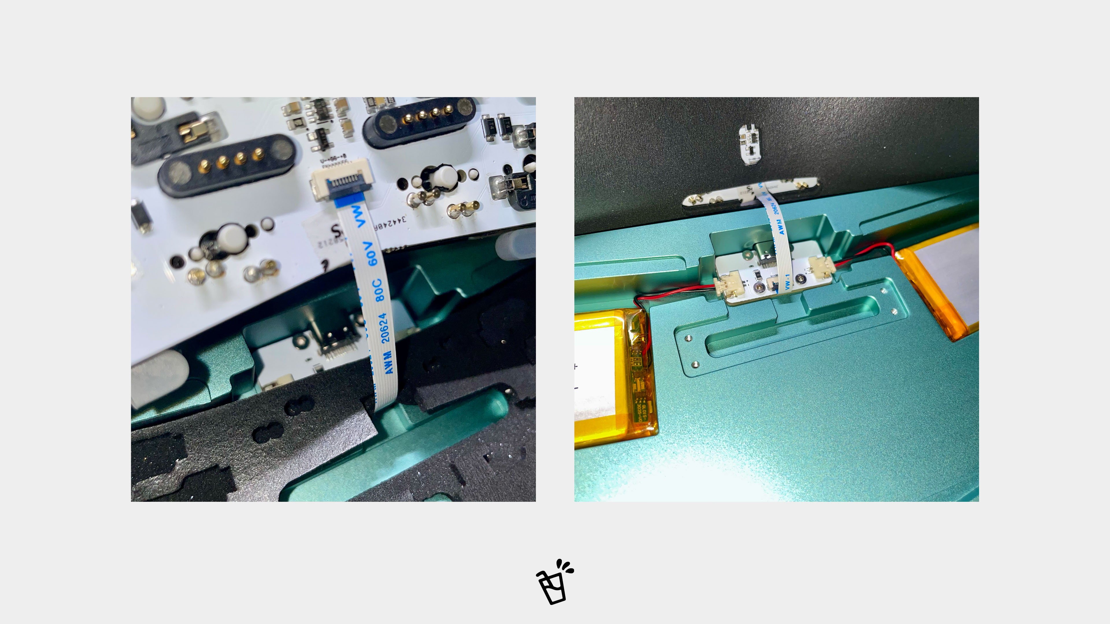
This method bypasses the magnetic connection, the PCB provides a direct FFC connection as a backup.
- Connect one end of the spare to the USB-C daughterboard. Route the other end through the case foam and PCB foam, then connect it to the FFC socket on the back of the PCB.
Note: Use the and insert it firmly.
- After connecting the FFC, tuck the cable neatly and connect the batteries on both sides as needed.
- The remaining assembly steps are identical to those described above.